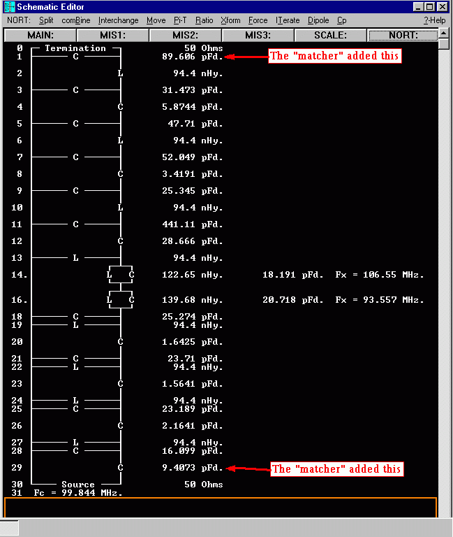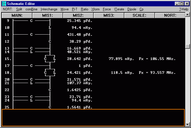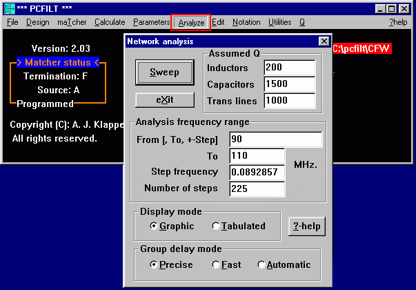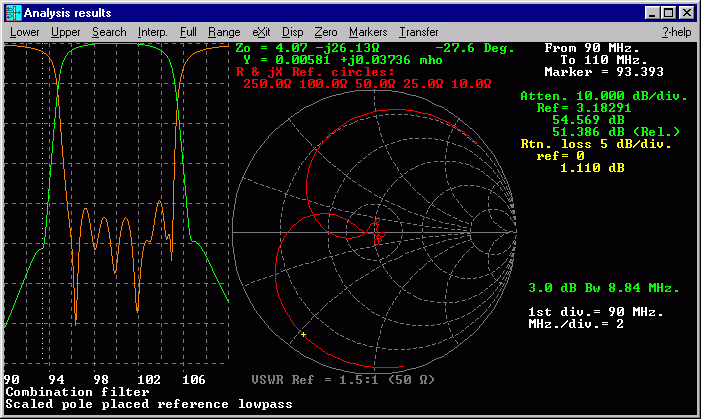
The rest of the screen shots are the Windows version
Here's the example:

*** Speed and Flexibility ***
To illustrate the power and flexibility of PCFILT, Here's an example.One quick way to design a bandpass filter is to simply scale it from anormalized lowpass filter. This method has been expanded to its logical limitwith the ability to scale any filter topology from any type of lowpass!
A typical PCFILT menu (The filter "type" menu from the DOS version) looks like this:

Let's make a 10% bandwidth filter at 100 MHz that has capacitively coupled parallel resonant sections at one end and shunt coupled series sections at the other. Just for good measure, we will stick two stopband "notch" sections in the middle by using the lowpass reference pole placer.

After you have selected the reference to be a pole-placed lowpass, the "Design Parameters" menu comes up automatically. This where you select the specifications for the filter.
Next, Set the 3rd coupling to be the inter-network dual ("D") and the rest as capacitors.


Here is the default reference lowpass filter that is synthesized by simply pressing the [Automatic] key (finite zero "notch" sections are placed in the middle of the network):


The "Matcher" gives you a list of optional networks to "tack-on" to each end of the filter to transform it from the "design impedance" (624.25 Ohms) to whatever you like, usually 50 Ohms.

Source end impedance matching options:


