What's wrong with the stock Klipsch crossover networks ?
What's wrong is
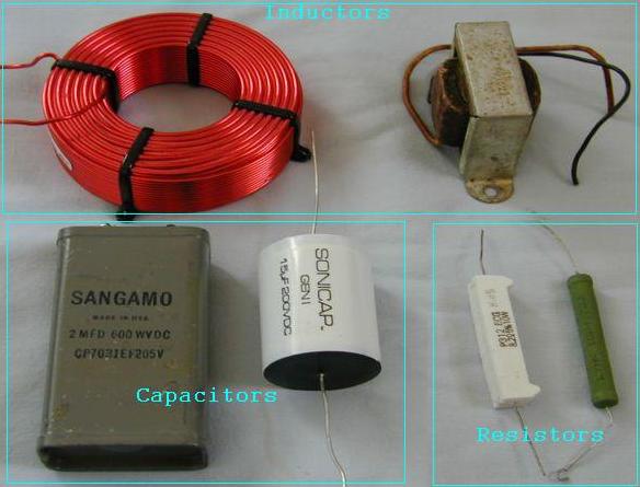
First, a quick course in very basic electronics is a must! There are three basic types of electronic components. The inductor, capacitor and resistor. Here is a quick explanation of the three.
-
Inductors. An inductor is a coil of wire. They act to provide anINcreasing opposition to the flow of current as frequency (pitch) goes up. They also force the current flowing through them to be out of step (+90 degrees phase shift) with the voltage applied to them. This is called inductive reactance. -
Capacitors. A capacitor consists of two metal plates insulated from each other by a very thin sheet of material such as paper, mylar or polypropylene. A capacitor offers aDEcreasing opposition to the flow of current as frequency goes up. The current flow through it is also out of step (-90 degrees phase shift) with the voltage applied to it, but it is exactly opposite of that associated with an inductor! This is called capacitive reactance. -
Resistors. A resistor is simply a BAD CONDUCTOR! It's like a very thin wire. It provides a stable opposition to current through it no matter the frequency. The current through it is exactly in step with the voltage applied to it. (0 degrees phase sift). A resistor is the only type of part that will turn electrical energy into heat. The heat represents "true" power. A capacitor and inductor draws only "wattless" power, They return energy drawn from the source in the second half of each cycle that was consumed in the first half! It's the result of the 90 degree phase difference between voltage and current. No heat is generated and no power is consumed no matter the current flow. A loudspeaker should look like a pure resistor to the amplifier.
Another term you will often hear is
All stereo power amplifiers are measured and specified as delivering power into a RESISTOR. That is, a load having no inductive or capacitive component and the current drawn in perfect step with the voltage applied. This is what a crossover network and loudspeaker should look like to the amp.
Below are impedance plots of the "AA' and ALK Universal networks comparing the impedance seen by the amp at all frequencies. The top two curves show the reactance phase of the impedance. It should be a straight line at ZERO degrees. Below zero indicates the amp is seeing a capacitor and a resistor. When the line is above zero the amp sees an inductor and a resistor.
The bottom two curves show the resistive error. Again the curve should be a straight line at 8 Ohms. Look at the AA at about 2000 Hz (the little red X). It's almost 30 Ohms! That's right in the most important spot in the midrange! All of the ALK networks look like pure resistors of 6 to 8 ohms over the entire audio range.
Here is a graphic to identify the parts of the Klipsch "AA" network and a listing of its problems

Some details about the design problems,
Problem(1) The AA has a single series connected inductor to limit the highs going to the woofer. It "looks" like an inductor to the amp. An equal and opposite amount of capacity is required to cancel the inductor. It's NOT THERE! It would be inserted between the amp and the rest of the crossover network. This would then be a correct 1st order constant-impedance "diplexer" at 400 Hz. What's actually there is just a high limiter for the woofer. To be more precise, the 13 uF cap (C1) would be in the position to perform this function, but its value is too low and the rest of the network would need to be modified. This is were problem(2) comes into play.Problem(2) 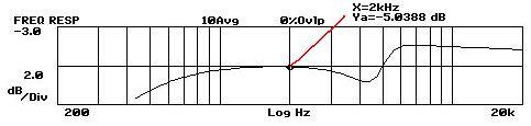 A capacitor allows high frequencies to pass and stops lows. Notice that the AA has a 13 uF cap (C1) connected directly to a 2 uF cap (C2). This means that highs all the way to 20 KHz are going to both the squawker and to the tweeter above 6000 Hz, where the tweeter filter cuts off. The measured performance of the AA squawker output shows this. That is a total NO-NO! Why send 20 KHz to a driver that can't go above 6000 Hz? The answer is so that no extra parts are required to actually "cross over" to the tweeter! The AA network actually DEPENDS on the K55 squawker driver naturally pooping out at 6000 Hz to form the crossover! As the little bird said "cheep, cheep"! Just like in the woofer section where the associated cap is missing, here an inductor is missing! Actually, what is missing is the parts that would form a lowpass having a "mirror image" reactance slope to that of the tweeter filter connected to limit the energy going to the squawker to 6000 Hz and below. This is what would be needed to make C1 work properly to resolve problem(1) if it were not for problem number(4)!
 Is this getting involved, or what? Problem(3) 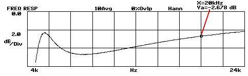 The tweeter filter, by Paul Klipsch's own admission, was designed using long-outmoded "constant K" methods. This method is for filters that are to be used between EQUAL impedances. It yields a symmetrical filter that can only operate smoothly between symmetrical load and source impedances. A tweeter is 8 Ohms and an amp is a voltage source. It's less that 1/10 of an ohm! It's WRONG! It results in a filter that has a very rough response and a lot of loss. The measured performance of the AA tweeter filter is shown. It has a 2 dB "sag" and 2.6 dB loss at 20 KHz! The loss is partly due to old dried out caps, but the "sag" is just bad design! As a matter of fact, component loss actually acts to mask this type of sag. If you replace the caps with new ones, the sag will get WORSE!
This situation requires a filter designed to operate between zero ohms and 8 Ohms. It's called a singly-terminated filter. Again, the opposite components required to form a constant impedance "diplexer" at 6000 Hz are missing.
Problem(4) The autotransformer (T2A) is used to reduce the level (loudness) of the squawker by 3 dB. A side effect of a transformer used this way is that the impedance looking into it is the square of the turns ratio times the impedance of its load. That's why the impedance seen by the amp rises to about 30 Ohms in the midrange! Mr. Klipsch allowed this because the capacitor required to limit the low range of the squawker (C1 in this case) gets smaller as the impedance goes up. If the impedance was held at 8 Ohms the 13 uF cap would have had to be MUCH larger. In his day, it would have been the size of Texas and cost a mint. These days that is no longer the case. There is simply no good reason to allow the impedance to go up using modern capacitors.Problem(5) The inductor in the tweeter filter (L2) is wound of small gauge solid wire to reduce cost. It has a quality factor (Q) of about 15 or 20. The inductors used by ALK are of thicker "Litz" wire and have Q ratings nearly 3 times higher. Litz wire has many strands of thinner wire each insulated from the others except at the very ends. Some AA networks even had this inductor mounted using a steel screw through the middle. This reduces both the inductance and the Q factor! Loss in a filter screws up the flatness of the response and divorces the driver from the amplifiers damping factor.Problem(6) Modern capacitors made of polypropylene reduce losses by a factor of 10. Even brand new mylar or paper caps have Q ratings of only 100 to 200. Even inexpensive Solen polypropylene caps have Q rating of over 1000. The capacitors even dry out over time and show very high internal series resistance. Q is actually defined as the ratio of internal series resistance to reactance.Problem(7) The Klipsch literature of the time the "AA" network was in production claimed the high crossover frequency was 6000 Hz. All of the discussion until now has assumed a 6000 Hz high crossover frequency. Look carefully at the measured performance plots of the "AA" squawker and tweeter outputs. The tweeter filter actually starts sending energy to the tweeter below 5000 Hz, not 6000 Hz! Every K55 driver I have tested has output to about 6000 Hz. This means BOTH the squawker and tweeter are generating full output between 5000 and 6000 Hz. That's not good! Early K55V drivers (the ones with push-pin connections) also had a "glitch" at 9000 Hz that the AA network can't deal with at all! That's part of probelm(2).
The initial goal was to develop a network to replace the AA in my own Belle Klipsch speakers that would be similar in scope to the "AA" but would bypass all these problems. Using the filter design techniques learned through many years of designing similar but far more aggressive networks at microwave frequencies, where these sort of errors could never be tolerated, a correct design was done. The result was the Universal network. It is basically a "corrected" AA. The schematic is below showing the actual changes to the AA to transform it into the ALK Universal.
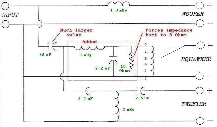
Then later.....
As time went on and more investigation was done it became obvious that more aggressive slopes to control interference between drivers would be a good thing. The literature always implied that filter slopes beyond about 18 dB / octave didn't sound good. It was also obvious to me that loudspeaker people simply didn't know how to design simple networks let alone more aggressive ones! This is most likely why attempts at sharper slopes were failures. Experience at microwave frequencies with L-C filters FAR more involved than anything that could fit in a loudspeaker would make an extreme-slope network having about 20 - 25 dB ultimate rejection at audio frequency a cake-walk. The extreme-slope network series was the result.
Al K.